+49 9622 719910

Solar Technology

The solar controller is the central control element of a solar off-grid system

The solar controller is the most important link between the photovoltaic module and the solar battery and therefore the central control element of the self-sufficient stand-alone system – because it manages the entire system.
 

IVT solar charge controllers guarantee a controlled charging process with the best possible charging result and optimum battery maintenance at all times, thanks to
  • different control technologies (serial, shunt, MPPT)
  • highly efficient charging procedures for all common battery types (lead-acid, lead-gel, lead-AGM, LiFePO4)
  • useful setting options and functions for individualised use


MPPT technology Serial charging regulation PWM Shunt charging regulation System voltage 12 V/24 V DC (48 V) Extensive protection functions CE 3 years warranty Made in Europe
 

IVT solar controllers product range

FAQ | Useful informations

Configuration of a solar island system

+

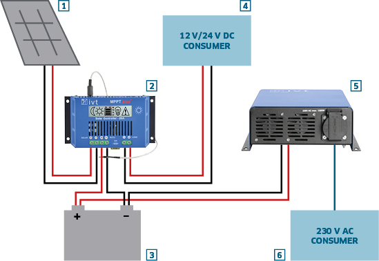
Graphic: Components of a solar island system


Installation of a 12 V/24 V off-grid system with DC and AC loads

Solar systems ensure an individual energy supply almost everywhere. An off-grid system for independent power supply with solar energy usually consists of several components, depending on the area of application:
 
Components of a solar island system
One or more solar module(s)
A solar charge controller
One or more solar battery(ies)
Optionally: a 12 V or 24 V direct current consumer (e.g. LED lighting)
An inverter if alternating current (230 V) is required
Alternating current consumer (e.g. 230 V AC lamps, TV set, tools)

Design and dimensioning of an off-grid solar system
  • The solar module (1) is connected to the solar controller (2). The two cables (±) used should be sufficiently sized to avoid line losses.
  • The charge controller (2) is connected to the solar battery (3) and, if necessary, to the DC consumers (4).
  • The charge controller should be dimensioned at least 10 % higher than the maximum current of the modules.
  • The battery cable and the cables to the loads should always contain an appropriate fuse.
  • The inverter (5) is always connected to the battery (3), never directly to the charge controller (2), as this can destroy the controller. This cable should also be fitted with a fuse.
  • The 230 V AC consumers (6) can be connected to the inverter (5).
  • The safety regulations for electrical installations must be observed during installation.

Please note: The solar batteries should be installed in a closed, dry room.

Why do you need a solar charge controller?

+
Solar controllers are used to supply solar energy to a suitable energy storage device in a controlled manner.

The sun's radiant energy is converted into electrical energy using a solar cell or solar module. The charge controller then ensures that this electrical energy is fed precisely and gently into a battery.

Solar controller: link between solar module and battery

Please note: Use suitable connection and connection cables to avoid losses on the lines.

The rechargeable battery as energy storage

+
Rechargeable batteries are used to store electrical energy. There are many different technologies on the battery market for constructing such an energy storage device. However, the most characteristic features are always the nominal voltage (V) and the capacity (Ah).
 

Why does it make sense to store surplus electricity?

When the sun is shining intensively, excess energy is often generated which should be stored for later use.

Benefits:
  • With solar power, you are independent of public power grids or where a reliable power supply cannot be guaranteed, e.g. when travelling in a motorhome or caravan, remote cabins and much more.
  • Power storage units provide self-generated solar power exactly when it is needed, usually in the evening and at night
  • Solar power is environmentally friendly due to the saving of fossil fuels


Which type of battery makes sense?

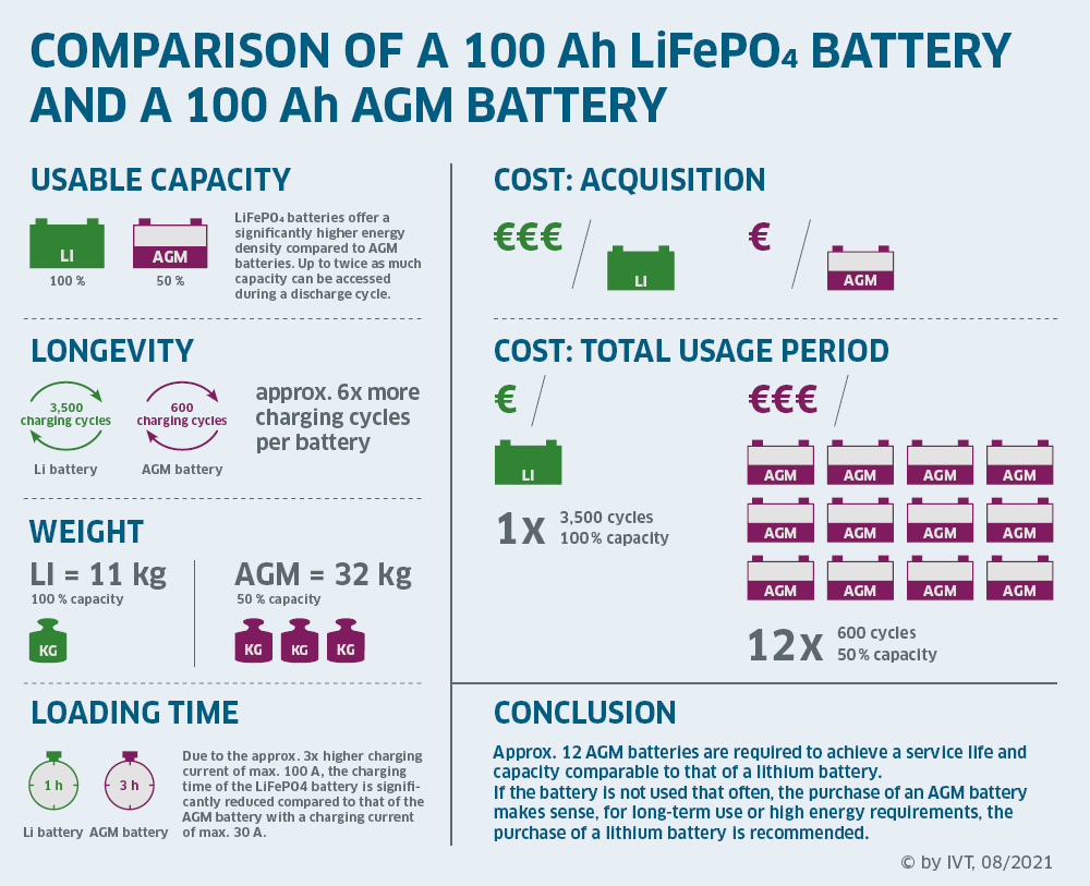
Lead-acid batteries are often used in the field of solar technology due to their favourable acquisition costs. Depending on the design, a distinction is made between classic, open lead-acid batteries, lead-gel batteries and lead-flow batteries or lead-AGM batteries. Many charge controllers are specially designed for this type of battery.

LiFePO4 batteries are the latest generation of energy storage systems and are suitable for replacing existing lead-acid battery systems. When switching to a LiFePO4 battery storage system, the charge controller settings must be checked and adjusted if necessary.

If you consider the costs over the entire period of use, a LiFePO4 system is more favourable. This is why the trend is increasingly moving towards LiFePO4 battery storage systems.
 
Infographic: Comparison of Lithium and AGM batteries | IVT GmbH

Solar module and brief description of charging process

+

What is a solar module or solar cell?

A solar module consists of several interconnected solar cells and is used to convert the radiative energy of the sun into electrical energy. Direct voltage is provided on the terminals of the radiated solar module. If the module is operated in a closed circuit, direct current flows.
 

Brief description of the charging process

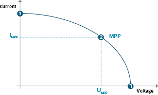
Graphic: Current/voltage characteristic of a solar module

Current/voltage characteristic of a solar module

(1) Short-circuit point
The solar module’s terminals are shorted, this means that the electrical resistance between the terminals is extremely low. The highest possible short circuit current IK of the solar module flows at this point.
(2) Maximum power point (MPP)
The solar module provides the highest possible power. This is the product of current IMPP and voltage UMPP in MPP.
(3) Idle point
At this point the solar module’s terminals are open, this means that the electrical resistance between the terminals is extremely high. The idle voltage of the solar module can be measured on the terminals.

The working point moves between point 1 and 3, depending on which electrical consumer is connected to the solar module.


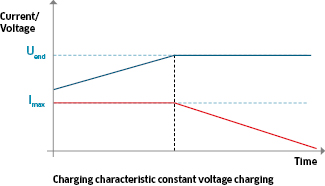
Graphic: Constant voltage charge


Charging with constant voltage (U-charging)
With constant voltage charging, the charging/cut-off voltage Uend is kept constant throughout the entire charging process. As a result, a higher current Imax flows at the beginning of the charging process than at the end.

Due to the decreasing current towards the end of the charging process, the battery is charged gently.

Graphic: PWM charge
    
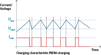
Charging by pulse-width-modulation (PWM)
When charging according to the pulse-width-modulation principle at the beginning of the charging process the battery is charged with maximum current Imax. As soon as the cut-off voltage Uend is reached, the current flow is stopped in order to avoid overcharging.

After this first charging step the battery is not fully charge most of the time. A decrease of the battery voltage is to be expected. For this reason, the charging current restarts if the voltage Ustart falls short of a certain value. This process is repeated until the battery is completely full. The charging current phases become shorter as the battery fills up.

Types of charging regulation

+

Brief description of the most important charging regulation methods

 
Graphic: Shunt regulation                             
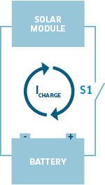
Shunt regulation

During the charging process the solar module is connected with the battery via charge controller and charging current Icharge is fed from the solar module to the battery. Yet, this process is only given if the solar voltage is higher than the required cut-off voltage of the battery. If this cut-off voltage is reached, this is recognized by the charge controller and the solar cell is shorted via contact S1. Thus, the current flow from the solar module to the battery is stopped. With this, overcharging and damage to the battery is prevented.

The entire current IK, provided by the solar module flows to the closed short circuit contact and will be converted to heat within the charge controller.

On the solar module diagram (chart 1) the working point moves to point 1 at full battery condition. During the charging process the working point is between point 1 and 2.

Advantages shunt regulation
  • Fast regulation
  • Simple switching mode

Disadvantages shunt regulation
  • Not suitable for high power
  • Solar power is not used in an optimum manner

 
 Graphic: Serial regulation 
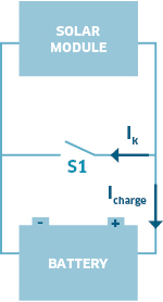
Serial regulation

The solar module is connected with the battery which is to be charged by means of the charge controller and charging current Icharge is fed into the battery. Yet, this process is only given if the solar voltage is higher than
the required cut-off voltage of the battery. If the cut-off voltage is reached, the charge controller detects this and disconnects the battery by means of the switch contact S1. With this, the current flow to the battery is stopped. Thus, overcharging and damage to the battery is prevented.

On the solar module diagram (chart 1) the working point moves to point 3 at full battery condition. During the charging process the working point is between 1 and 2.

Advantages serial regulation
  • Also suitable for higher power
  • Simple switching mode

Disadvantage serial regulation
  • Solar power is not used in an optimum manner


Graphic: MPPT regulation

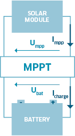
MPPT regulation

By virtue of the Maximum Power Point Tracker (MPPT) it is achieved that at all times the maximum possible solar power Pmpp is converted into the maximum possible charging power Pbat for the connected battery.

Pmpp = Pbat

Umpp • Impp = Ubat • Ibat

The MPPT function determines the working point of the solar panel at which the maximum solar power Pmpp is available (chart 1, point 2). This maximum power is processed by the MPPT into the required battery charging voltage Ubat and the corresponding charging current Icharge. Charge controllers without this function are not able to process excessive voltage.

Charge controllers with this function are able to also take advantage of the excessive voltage.

Advantages MPPT regulation
  • Solar power is used in an optimum manner
  • Suitable for solar modules with higher voltage

Disadvantage MPPT regulation
  • Complex switching electronic

Brief description of the most important charging regulation methods

 
Graphic: Shunt regulation

Shunt regulation

During the charging process the solar module is connected with the battery via charge controller and charging current Icharge is fed from the solar module to the battery. Yet, this process is only given if the solar voltage is higher than the required cut-off voltage of the battery. If this cut-off voltage is reached, this is recognized by the charge controller and the solar cell is shorted via contact S1. Thus, the current flow from the solar module to the battery is stopped. With this, overcharging and damage to the battery is prevented.

The entire current IK, provided by the solar module flows to the closed short circuit contact and will be converted to heat within the charge controller.

On the solar module diagram (chart 1) the working point moves to point 1 at full battery condition. During the charging process the working point is between point 1 and 2.

Advantages shunt regulation
  • Fast regulation
  • Simple switching mode

Disadvantages shunt regulation
  • Not suitable for high power
  • Solar power is not used in an optimum manner


 Graphic: Serial regulation

Serial regulation

The solar module is connected with the battery which is to be charged by means of the charge controller and charging current Icharge is fed into the battery. Yet, this process is only given if the solar voltage is higher than
the required cut-off voltage of the battery. If the cut-off voltage is reached, the charge controller detects this and disconnects the battery by means of the switch contact S1. With this, the current flow to the battery is stopped. Thus, overcharging and damage to the battery is prevented.

On the solar module diagram (chart 1) the working point moves to point 3 at full battery condition. During the charging process the working point is between 1 and 2.

Advantages serial regulation
  • Also suitable for higher power
  • Simple switching mode

Disadvantage serial regulation
  • Solar power is not used in an optimum manner


Graphic: MPPT regulation

MPPT regulation

By virtue of the Maximum Power Point Tracker (MPPT) it is achieved that at all times the maximum possible solar power Pmpp is converted into the maximum possible charging power Pbat for the connected battery.

Pmpp = Pbat

Umpp • Impp = Ubat • Ibat

The MPPT function determines the working point of the solar panel at which the maximum solar power Pmpp is available (chart 1, point 2). This maximum power is processed by the MPPT into the required battery charging voltage Ubat and the corresponding charging current Icharge. Charge controllers without this function are not able to process excessive voltage.

Charge controllers with this function are able to also take advantage of the excessive voltage.

Advantages MPPT regulation
  • Solar power is used in an optimum manner
  • Suitable for solar modules with higher voltage

Disadvantage MPPT regulation
  • Complex switching electronic


Our plus: Coordinated solar components

IVT plans your customised solar island system

We support you in planning your customised stand-alone solar system

Sometimes you need customised solutions. We will be happy to advise you on the planning of your solar system, modify our products according to your ideas or manufacture products according to your wishes. Get in touch with us.

Customised solar island system questionnaire

We support you in putting together your customised solar island system.
 
Simply download the IVT solar questionnaire, fill it in and send it back to us. You will receive your customised offer within a few days.

Download questionnaire >
 

Solar power to go – 230 V, 12 V, 5 V USB

Portable Power Stations 600 W – 2000 W

Flexibly rechargeable
The portable IVT Power Stations offer you a self-sufficient power supply wherever and whenever you need it: on the road or stationary, for commercial or private use.
 
The powerful LiFePO4 battery can be charged flexibly: while travelling in the vehicle using an integrated 12 V charging booster, completely independently using solar power thanks to the built-in solar controller or at any 230 V socket with the enclosed 10 A battery charger.

Choose one of our pre-configured complete solutions or, with the help of our technicians, put together your own customised power station to suit your needs.

Further information on the Mobile Power Stations >
.